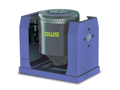
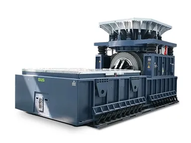
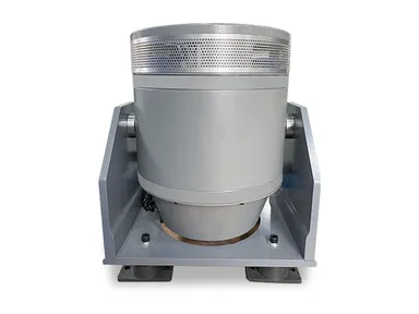
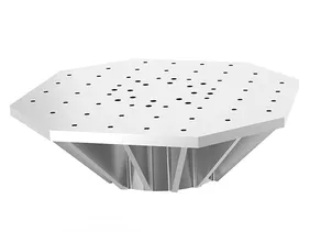
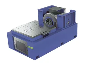
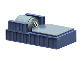
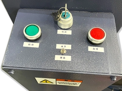
We focus on developing and manufacturing electromagnetic vibration test systems that accurately recreate dynamic conditions encountered by products in real-world applications. The vibration test systems we offer, cover a wide range of force ratings, from 500 N up to 400 kN, with operating frequencies between 1 and 10,000 Hz. They are commonly used in industries such as automotive, aerospace, electronics, and renewable energy to verify product durability and ensure compliance with performance standards over the entire lifecycle.
Vibration describes the repetitive movement of a body or component away from its resting position. While this motion is common, it often poses challenges in real-world applications. Excessive or uncontrolled vibrations can lead to progressive deterioration of structural elements, functional malfunctions, unplanned shutdowns, or, in severe cases, catastrophic failures.
Conducting vibration tests is a proven method to prevent these issues. By replicating the dynamic conditions that occur during transportation, installation, and daily operation, vibration testing helps engineers assess how well a product can endure mechanical stress. This evaluation is critical for uncovering design weaknesses, confirming structural robustness, and validating that the equipment meets durability expectations under demanding conditions.
Electrodynamic shakers generate controlled vibratory forces through electromagnetic interaction. Inside the vibration test system, a fixed magnetic circuit, composed of a central pole, a cylindrical yoke, and a precisely engineered air gap, produces a stable, high-density magnetic field when the excitation coil receives direct current.
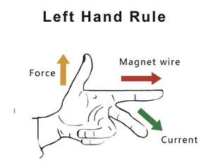
Suspended within this field is a moving assembly, often referred to as the armature or moving coil system, which is anchored by a suspension mechanism to maintain alignment. When alternating current is introduced into the drive coil, the coil interacts with the magnetic flux lines, creating a force that drives the armature and the attached table to oscillate. This conversion of electrical input into mechanical motion allows precise simulation of vibration profiles. According to Ampère’s law, the resulting electromagnetic force is directly proportional to the drive current, the effective length of the coil conductors, and the intensity of the magnetic field in the gap. In equation form: F = B × L × I, where F is the generated force, B is the magnetic flux density, L is the conductor length, and I is the current.
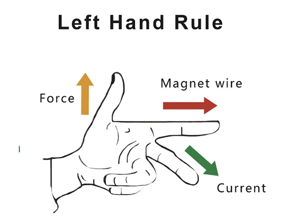
F: Electromagnetic Force (N) The force generated in the moving coil
B: Magnetic Flux Density (T) The strength of the magnetic field within the air gap
I: Current in the Coil (A) The magnitude of the alternating current flowing through the conductors
L: Effective Conductor Length (m) The length of the conductor interacting with the magnetic field

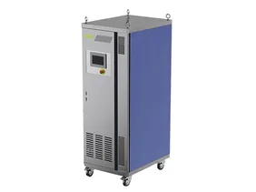
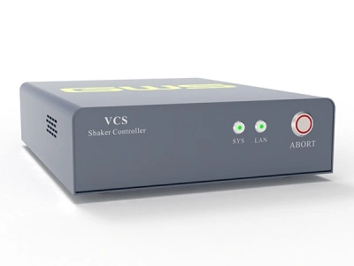
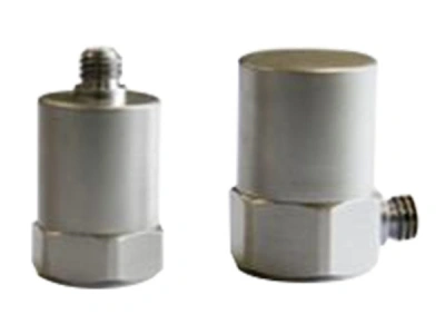
An electrodynamic vibration system functions as a closed-loop feedback platform composed of an electrodynamic shaker, a dedicated power amplifier, a cooling module, a vibration controller, and measurement instruments such as accelerometers.
During operation, the controller generates a finely balanced low-power drive signal, which the amplifier boosts and transmits to the shaker’s drive coil. This interaction produces controlled movement in the moving assembly. Throughout the test, the accelerometer captures vibration data in real time and relays it back to the controller, enabling continuous correction and stabilization of the drive signal to keep the vibration response within the desired profile. To prevent overheating and maintain performance consistency, an appropriate cooling solution, either air or water cooling, is integrated to remove excess heat generated during extended operation.
- Test conditions
Define what you expect: acceleration levels, velocity, displacement limits, frequency range, and vibration direction. These factors determine if the vibration test system can match your testing goals. - Test type
Specify the type of simulation you need, sine vibration, random vibration, shock testing, or a combined environmental scenario. This ensures the setup is tailored to your specific standards. - Specimen information
Provide details about the test item’s weight, dimensions, and center of gravity. Knowing this helps select a system that will handle the load safely and deliver reliable results.
- Step 1 - Select a suitable slip table and head expander based on your specimen’s dimensions and the intended vibration direction. You can refer to the specifications catalog for the weight of these accessories.
- Step 2 - Choose an estimated moving element (armature) mass as a reference.
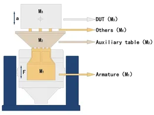
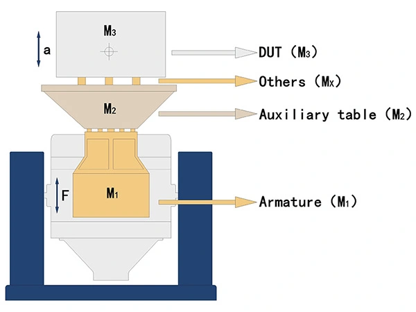
- Step 3 - Calculate the necessary excitation force using this formula:
F = (m1 + m2 + m3 … + mx) × a
where:
F = excitation force (N)
m1 = armature mass (kg)
m2 = auxiliary table mass (head expander or slip table) (kg)
m3 = specimen mass (kg)
mx = other masses (fixtures, bolts, etc.) (kg)
a = peak acceleration required by the test (m/s²)
Let’s say you have a test specimen that weighs 20 kg, measuring 280 × 280 mm. The fixture you’ll use weighs 10 kg. The maximum acceleration you plan to apply is 15 g, and you only need testing in the vertical (Z) direction.
For this example, we’ll reference the TS10-240 vibration system, whose moving element (armature) has an estimated mass of 10 kg.
Calculation Inputs:
- m1 – Armature mass: 10 kg
- m2 – Mass of the head expander: 10 kg
- m3 – Specimen mass: 20 kg
- mx – Additional mass (fixtures, bolts, etc.): 10 kg
- a – Target peak acceleration: 15 g (which equals 15 × 9.8 = 147 m/s²)
Calculation:
Excitation Force (F) = (m1 + m2 + m3 + mx) × a = (10 + 10 + 20 + 10) × 147 = 7350 N
So, to achieve the required test conditions, you would need a system capable of delivering at least 7350 newtons of excitation force.
Because fixtures and test specimens can introduce their own frequency response characteristics, it’s recommended to include at least 20% extra margin when determining the required force rating.
In this example:
- The calculated force was 7350 N.
- Applying a 1.2 safety factor: N × 1.2 = 8820 N
Since the TS10-240 system has a rated sine force output of 10,000 N, this setup provides sufficient capacity to handle the test safely and reliably.

In this example, choosing the TS10-240 vibration system covers the target force requirements with an adequate safety margin. If the total calculated force plus the extra allowance had surpassed the vibration shaker’s rated capacity, the next step would be to look at a higher-force model and re-run the calculations to make sure it fits the application. This process should continue until all testing demands are reliably met.


